 |
|
| |
|
|
ҵ��Ǣ̸��
��ϵ�ˣ���˳ƽ
�ֻ���17727550196����ͬ�ţ�
QQ:3003262363
EMAIL:zsp2018@szczkjgs.com
��ϵ�ˣ�۳�Ȼ�
�ֻ���17727552449 ����ͬ�ţ�
QQ:2850985542
EMAIL:yanxianhui@szczkjgs.com
���������緽ʽ��
�ֻ���13713728695����ͬ�ţ�
QQ:3003207580
EMAIL:panbo@szczkjgs.com
��ϵ�ˣ��˲� |
|
|
| |
|
 |
|
 |
��ǰλ�ã���ҳ -> ������� |
|
|
| TIDA��00281����48V 1kW������������ |
|
|
| ������Դ�� ����ʱ�䣺2016/6/21 13:26:00 |
|
TI��˾��TIDA-00281�Dz���UCC27201A-Q1��ƵN��MOSFET������������48V 1kW���������ο����,�ܴ����ߴ�30A�ĵ���,������C2000 LaunchPad���ӵ�ģ���·,����Ҫλ�ô��������ܿ���������ˢֱ������(BLDC),��48V���ϵͳ����,���й�ѹ,Ƿѹ,����,������˲ʱ���ϱ���.���Ľ�����UCC27201A-Q1��Ҫ����,���ܿ�ͼ,Ӧ�õ�·ͼ�Լ�TIDA-00281����48V 1kW BLDC���������ο������Ҫ����,ϵͳָ��,Ӧ�ÿ�ͼ,��·ͼ�Ͳ����嵥�Լ�pcb���ͼ.
The UCC27201A-Q1 high frequency N-Channel MOSFET driver includes a 120-V bootstrap diode and high-side/low-side driver with independent inputs for maximum control flexibility. This allows for N-Channel MOSFET control in half-bridge, full-bridge, two-switch forward and active clamp forward converters. The low-side and the high-side gate drivers are independently controlled and matched to 1-ns between the turn-on and turn-off of each other. The UCC27201A-Q1 is based on the popular UCC27200 and UCC27201 drivers, but offer some enhancements. In order to improve performance in noisy power supply environments the UCC27201A-Q1 has the ability to withstand a maximum of -18 V on its HS pin.
An on-chip bootstrap diode eliminates the external discrete diodes. Under-voltage lockout is provided for both the high-side and the low-side drivers forcing the outputs low if the drive voltage is below the specified threshold.
The UCC27201A-Q1 has TTL-compatible thresholds and is offered in a 10-Pin VSON and an 8-pin SOIC with a thermal pad.
UCC27201A-Q1��Ҫ����:
Qualified for Automotive Applications
AEC-Q100 Qualified With the Following Results:
Device Temperature Grade 1: �C40�� to 140�� Ambient Operating Temperature Range
Device HBM Classification Level 1C
Device CDM Classification Level C3
Negative Voltage Handling on HS (�C18 V)
Drives Two N-Channel MOSFETs in High-Side/Low-Side Configuration
Maximum Boot Voltage: 120 V
Maximum VDD Voltage: 20 V
On-Chip 0.65-V VF, 0.6-�� RD Bootstrap Diode
Greater than 1 MHz of Operation
20-ns Propagation Delay Times
3-A Sink, 3-A Source Output Currents
8-ns Rise and 7-ns Fall Time with 1000-pF Load
1-ns Delay Matching
Under Voltage Lockout for High-Side and Low-Side Driver
Offered in 8-Pin PowerPad SOIC-8 (DDA) and 10-Pin VSON (DMK) Packages
UCC27201A-Q1Ӧ��:
Auxiliary Inverters
DC-to-DC Converters for Power Train
Switch Mode Power Supplies
Motor Control
Half-Bridge Applications and Full-Bridge Converters
Two-Switch Forward Converters
Active-Clamp Forward Converters
High Voltage Synchronous-Buck Converters
Class-D Audio Amplifiers
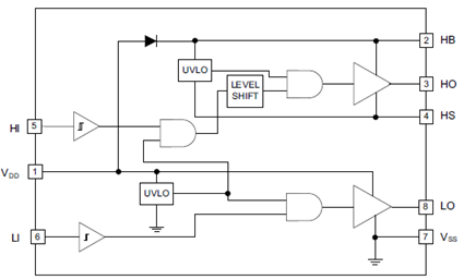
ͼ1.UCC27201A-Q1���ܿ�ͼ
ͼ2.UCC27201A-Q1��������ת������·
TIDA-00281����48V 1kW BLDC������������
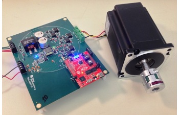
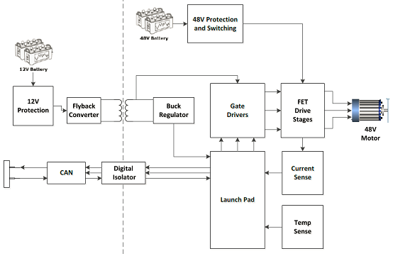
The TIDA-00281 TI Design is a 3-Phase Brushless DC Motor Drive designed to operate in 48-V automotive applications. The board is designed to drive motors in the 1-kW range and can handle currents up to 30-A. The design includes analog circuits working in conjunction with a C2000 LaunchPad to spin a 3-Phase BLDC motor without the need for position feedback from Hall Effect sensors or quadrature encoder.
TIDA-00281�ο������Ҫ����:
• Speed Control of 3-Phase Brushless DC (BLDC)Motors With no Position Sensors Needed
• Phase Voltage and Current Sensing Scaled andFiltered Feedback for Control of 3-Phase Power
• Operates Over Wide Range of Voltages From48-V Battery System
• Protection Against Overvoltage, Undervoltage,Overtemperature, Overcurrent, and TransientFaults
• Reverse Polarity Protection on 12-V Battery
• Isolated CAN Interface Connects to AutomotiveNetworks on 12-V Battery System
• Critical Components Fit in a 5-inch DiameterCircular PCB
• Components Selected for AutomotiveTemperature and Quality
• Test Points Provide Easy Access to Key MotorSignals
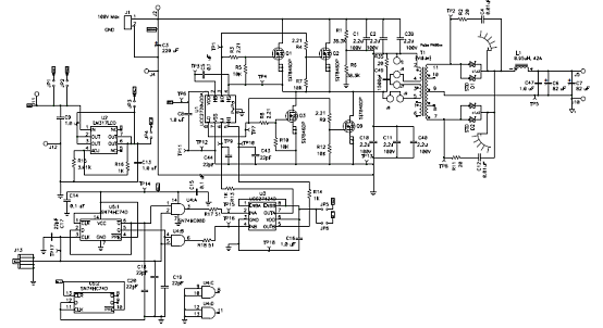
ͼ3.TIDA-00281����48V 1kW BLDC���������ο��������ͼ
TIDA-00281�ο����Ӧ��:
• Water Pump
• eTurbo
• Radiator Fan
• HVAC Blower
• Oil Pump
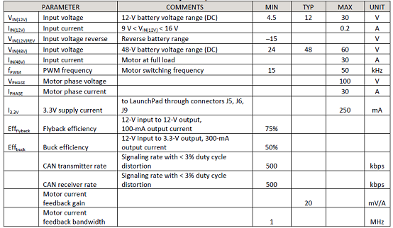
TIDA-00281�ο����ϵͳָ��:
ͼ4.TIDA-00281�ο���Ƹ���ͼ
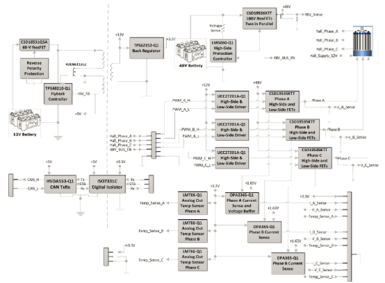
ͼ5.TIDA-00281�ο���ƿ�ͼ
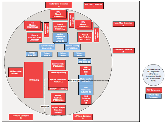
ͼ6.TIDA-00281�ο���ư��ƽ��ͼ
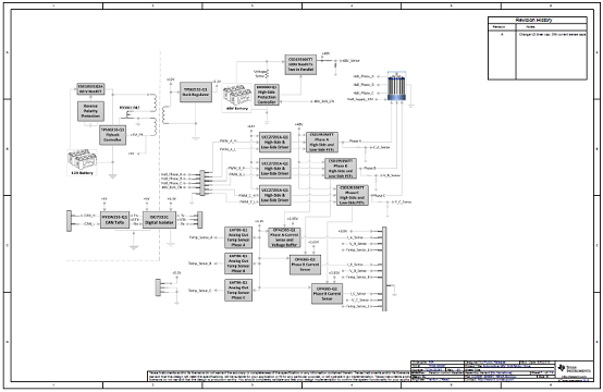
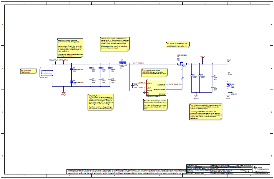
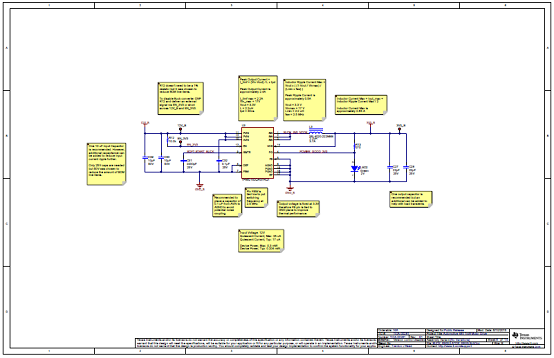
ͼ7.TIDA-00281�ο���ư��·ͼ(1)
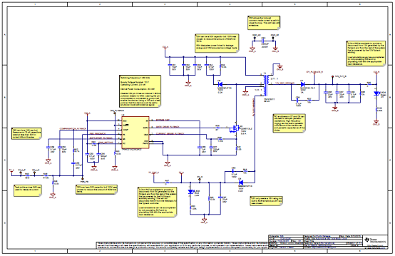
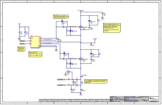
ͼ8.TIDA-00281�ο���ư��·ͼ(2)
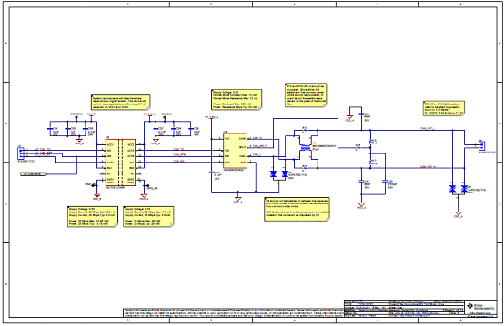
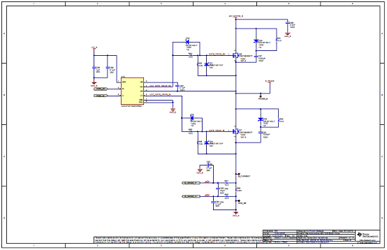
ͼ9.TIDA-00281�ο���ư��·ͼ(3)
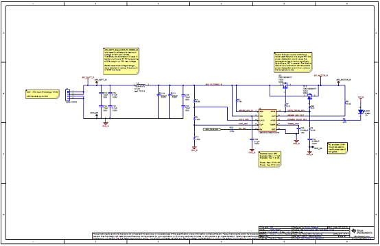
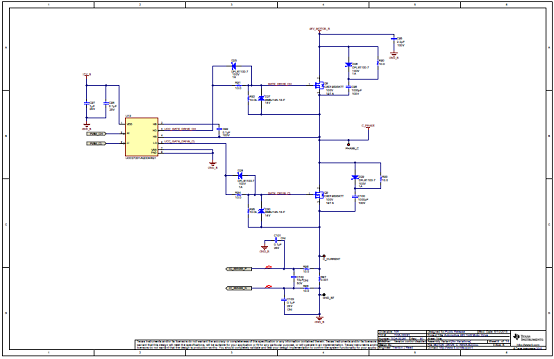
ͼ10.TIDA-00281�ο���ư��·ͼ(4)
ͼ11.TIDA-00281�ο���ư��·ͼ(5)
ͼ12.TIDA-00281�ο���ư��·ͼ(6)
ͼ13.TIDA-00281�ο���ư��·ͼ(7)
ͼ14.TIDA-00281�ο���ư��·ͼ(8)
ͼ15.TIDA-00281�ο���ư��·ͼ(9)
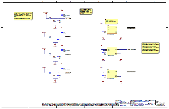
ͼ16.TIDA-00281�ο���ư��·ͼ(10)

ͼ17.TIDA-00281�ο���ư��·ͼ(11)
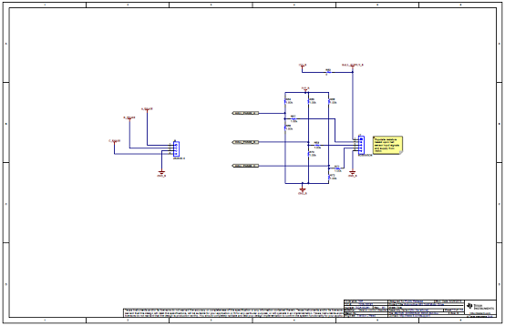
ͼ18.TIDA-00281�ο���ư��·ͼ(12)
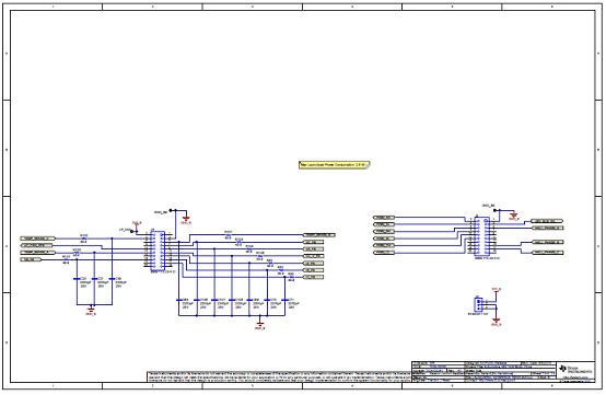
ͼ19.TIDA-00281�ο���ư��·ͼ(13)
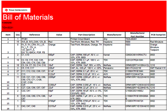
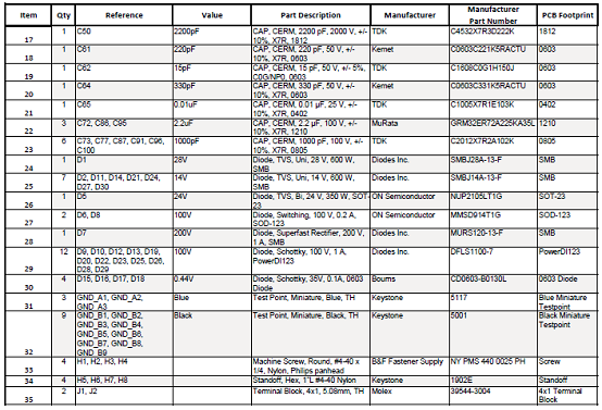
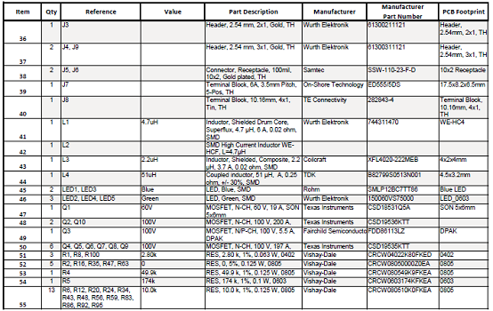
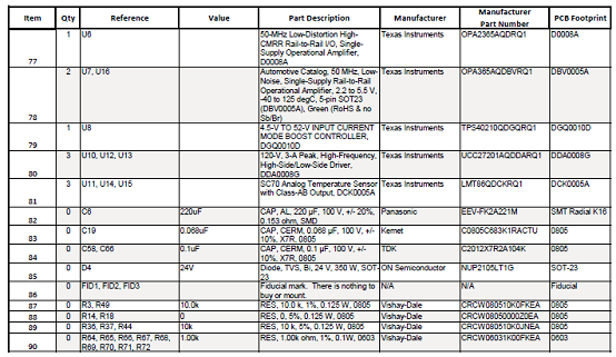
TIDA-00281�ο���ư�����嵥:
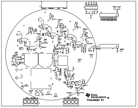
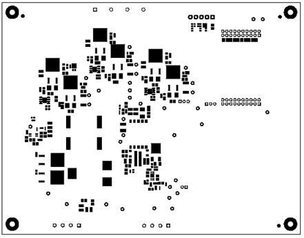
ͼ20.TIDA-00281�ο���ư�PCB���ͼ(1)
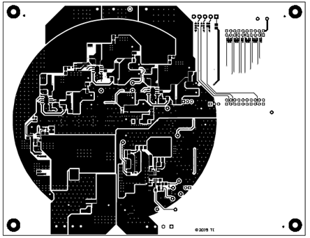
ͼ21.TIDA-00281�ο���ư�PCB���ͼ(2)
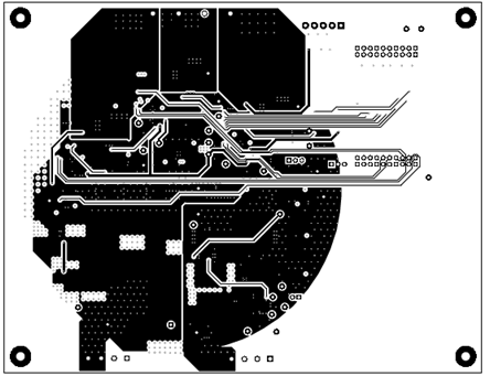
ͼ22.TIDA-00281�ο���ư�PCB���ͼ(3)
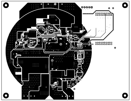
ͼ23.TIDA-00281�ο���ư�PCB���ͼ(4)
ͼ24.TIDA-00281�ο���ư�PCB���ͼ(5)
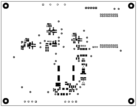
ͼ25.TIDA-00281�ο���ư�PCB���ͼ(6)
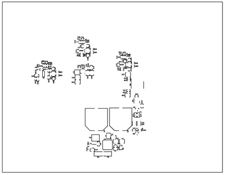
ͼ26.TIDA-00281�ο���ư�PCB���ͼ(7)
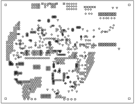
ͼ27.TIDA-00281�ο���ư�PCB���ͼ(8) |
|
| |
| |
|
|
|