 |
|
| |
|
|
业务洽谈:
联系人:张顺平
手机:17727550196(微信同号)
QQ:3003262363
EMAIL:zsp2018@szczkjgs.com
联系人:鄢先辉
手机:17727552449 (微信同号)
QQ:2850985542
EMAIL:yanxianhui@szczkjgs.com
负责人联络方式:
手机:13713728695(微信同号)
QQ:3003207580
EMAIL:panbo@szczkjgs.com
联系人:潘波 |
|
|
| |
|
 |
|
 |
当前位置:首页 -> 方案设计 |
|
|
| CS1680调光7W LED驱动器解决方案 |
|
|
| 文章来源: 更新时间:2015/6/18 9:51:00 |
|
Cirrus公司的CS1680是低压照明的可调光LED驱动器,具有最好的变压器兼容性,调光特性以及高达83%的效率,最低调光量5%,输出电压12V/15V,主要用在MR16灯和所有的12VAC/DC低压照明应用.本文介绍了CS1680主要特性,框图和应用电路,以及CRD1680-7W 7 W参考设计主要特性,电路图,材料清单和PCB设计图.
The CS1680 is a cascade boost-buck dimmable LEDdriver for the 12V halogen lamp-replacement market.
The CS1680 uses a Cirrus Logic proprietary intelligentdigital control that provides exceptional single-lamp andmulti-lamp transformer compatibility for non-dimmer systemsand dimmer systems paired with electronic andmagnetic low-voltage transformers.
The CS1680 integrates a continuous conduction mode(CCM) boost converter that provides transformer compatibilityand dimmer compatibility. An adaptive digitalalgorithm controls the boost stage and dimmer compatibilityoperation mode to enable flicker-free operationdown to 5% output current with leading-edge and trailing-edge dimmers.
CS1680主要特性:
• Best-in-class Transformer Compatibility
- Magnetic Transformers
- Electronic Transformers
• Best-in-class Dimmer Compatibility
- Leading-edge (TRIAC) Dimmers
- Trailing-edge Dimmers
• High Efficiency
- Up to 80% for CS1680-00 Applications
- Up to 83% for CS1680-02 Applications
• Flicker-free Dimming
• 5% Minimum Dimming Level
• Cascade Boost-buck Topology with Constant-currentOutput
- CS1680-00 Output Voltage 15V
- CS1680-02 Output Voltage 21V
• Fast Startup
• Tight LED Current Regulation: Better than ±10%
• >0.9 Power Factor on Magnetic Transformers
• Soft Start
• Protections:
-Output Open/Short
- Boost Overvoltage
-Overcurrent Detection
- External Overtemperature Using NTC
CS1680应用:
• MR16 Lamps
• All 12VAC/VDC Low-voltage Lighting Applications
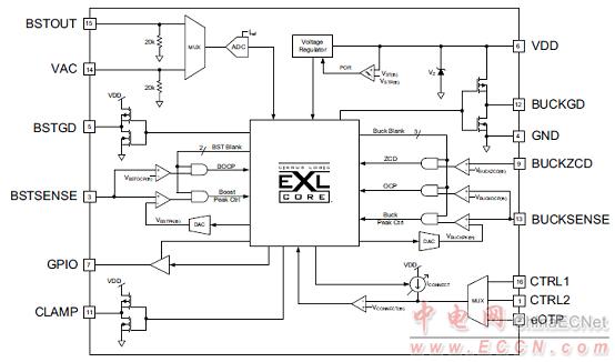
图1.CS1680框图
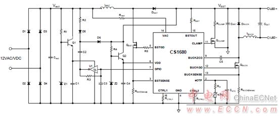
图2.CS1680应用电路图
CRD1680-7W 7 W参考设计
The CRD1680-7W reference design demonstrates theperformance of the CS1680 dimmable LED driver forlow-voltage lighting with a target output of 430mA driving4LEDs in series. It provides exceptional single-lampand multi-lamp transformer compatibility for non-dimmersystems and dimmer systems paired with electronic andmagnetic low-voltage transformers. The form factor istargeted to fit into MR16 LED lamp applications.
The CRD1680-7W board is optimized to deliver low system cost in a high-efficiency, flicker-free, phase-dimmable,solid-state lighting (SSL) solution for incandescent lamp replacement applications. The feedback loop is closedthrough an integrated digital control system within the IC. Protection algorithms such as output open/short, overcurrentdetection, boost overvoltage, and overtemperature thermistors protect the system during abnormal conditions.
Details of these features are provided in the CS1680 Dimmable LED Driver IC for Low-voltage Lighting data sheet.
The CRD1680-7W board demonstrates the performance of the CS1680. This reference board has been designedfor an output load of 4LEDs in series at a target output current of 430mA (12.0V typical).
This document provides the schematic for the board. It includes oscilloscope screen shots that indicate various operatingwaveforms. Graphs are also provided that document the performance of the board in terms of Efficiency vs.Line Voltage, Output Current vs. Line Voltage, and Output Current vs. Dim Angle for the CS1680 dimmable LEDcontroller IC.
CRD1680-7W 7 W参考设计特性:
• Constant-current Output
• Flicker-free Dimming
• Line Voltage 12VAC/VDC, ±10%
• Rated Input Power: 7.0W
• Rated Output Power: 5.6W
• Output Voltage: <15V
• High Efficiency with Magnetic and ElectronicTransformers
• Low Component Count
• Supports Cirrus Logic Product CS1680
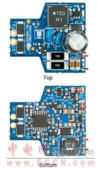
图3.CRD1680-7W 7 W参考设计外形图
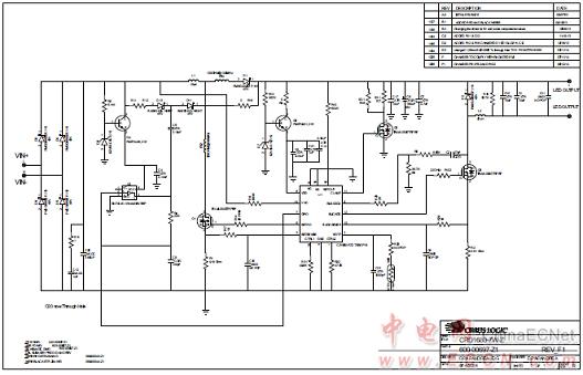
图4.CRD1680-7W 7 W参考设计电路图
CRD1680-7W 7 W参考设计材料清单:
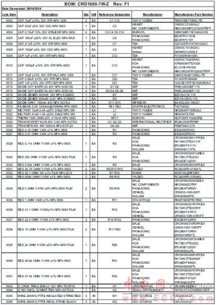
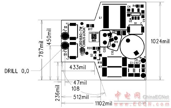
图5.CRD1680-7W 7 W参考设计PCB尺寸
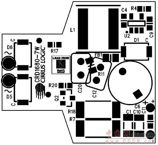
图6.CRD1680-7W 7 W参考设计PCB顶层丝印图
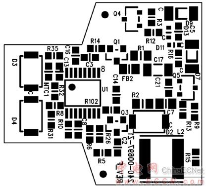
图7.CRD1680-7W 7 W参考设计PCB底层丝印图
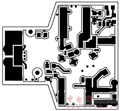
图8.CRD1680-7W 7 W参考设计PCB走线图(层1)
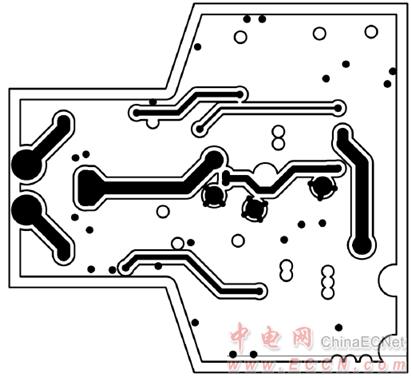
图9.CRD1680-7W 7 W参考设计PCB走线图(层2)
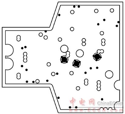
图10.CRD1680-7W 7 W参考设计PCB走线图(层3)
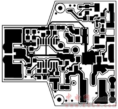
图11.CRD1680-7W 7 W参考设计PCB走线图(层4) |
|
| |
| |
|
|
|

